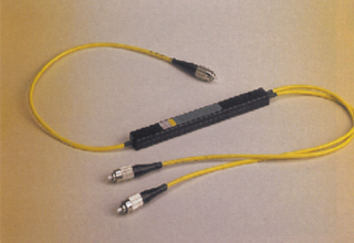
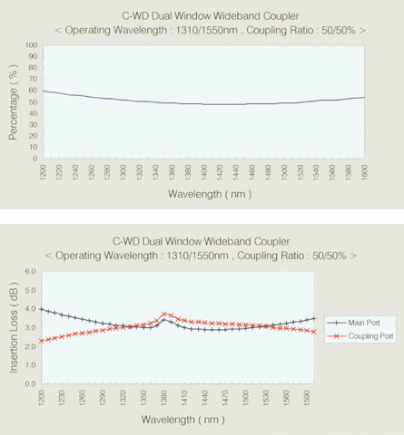
The C-WD series is a wideband coupler that works in both the 1310 nm and 1550 nm windows. It is available in 1x2 and 2x2 port configurations with coupling ratios from 1:99 to 50:50, and is used in telecommunications, LAN, FTTH, video transmission, fiber optic sensing, CATV and test equipment.
Features
- Low insertion loss
- High port isolation
- Custom defined specifications
- Environmentally stable
Applications
- Telecommunications
- Local area network
- Fiber to the home
- Video transmission
- Fiber optic sensing
- Test instruments and CATV
Performance specifications
| Item | Super grade (S) | High grade (H) |
|---|---|---|
| Operating wavelength (nm) | 1310 ± 40 and 1550 ± 40 | 1310 ± 40 and 1550 ± 40 |
| Typical excess loss (dB) | 0.08 | 0.2 |
| Uniformity (dB, 50:50) | 0.8 | 1.2 |
| Thermal stability (dB peak-peak) | <0.2 | <0.3 |
| Polarization stability (dB) | <0.10 | <0.15 |
| Port configuration | 1 x 2 or 2 x 2 | 1 x 2 or 2 x 2 |
| Coupling ratio | 1:99 to 50:50 (50:50 standard) | 1:99 to 50:50 (50:50 standard) |
| Directivity (dB) | >50 (1x2), >60 (2x2) | >50 (1x2), >60 (2x2) |
| Reflectance (dB) | <-55 | <-55 |
| Operating temperature (C) | -40 to +85 | -40 to +85 |
| Storage temperature (C) | -55 to +85 | -55 to +85 |
If the table is wider than the screen, scroll sideways to see every column.
Coupling ratio vs. insertion loss
| Coupling ratio (%) | Super grade (S) insertion loss (dB) | High grade (H) insertion loss (dB) |
|---|---|---|
| 50 / 50 | 3.6 | 3.8 |
| 45 / 55 | 3.6 / 3.15 | 4.45 / 3.3 |
| 40 / 60 | 4.7 / 2.7 | 5.0 / 2.9 |
| 35 / 65 | 5.35 / 2.3 | 5.7 / 2.5 |
| 30 / 70 | 6.0 / 1.9 | 6.4 / 2.1 |
| 25 / 75 | 6.95 / 1.7 | 7.45 / 1.9 |
| 20 / 80 | 7.9 / 1.4 | 8.5 / 1.5 |
| 15 / 85 | 9.6 / 1.0 | 10.6 / 1.1 |
| 10 / 90 | 11.0 / 0.7 | 12.7 / 0.8 |
| 5 / 95 | 14.6 / 0.5 | 18.4 / 0.55 |
| 1 / 99 | 21.6 / 0.3 | 21.6 / 0.4 |
If the table is wider than the screen, scroll sideways to see every column.
Where two values are shown, they are the insertion losses of the two output ports in order. The datasheet is available on request.
Package options (pigtailing)
| Package option | Option code |
|---|---|
| 01. Coated fiber (250 um) | T5, MA, MB |
| 02. Loose tube (900 um) | TA, MA, MB |
| 03. PVC cable (3.0 mm) | A1, MA, MB |
If the table is wider than the screen, scroll sideways to see every column.
Ask us about coupler specifications
Tell us the wavelength, port configuration, coupling ratio and pigtailing type.